Lights & Lasers

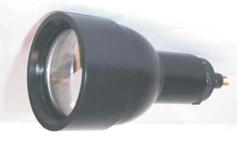
SS172 Sea Torch Halogen Light
Field-serviceable aluminum subsea halogen light with selectable reflector and lamp.
Explore productInspection Systems
Portable guide-wire video inspection package for subsea riser and BOP monitoring.
Inspection system integration · Reference SYS-SI-GUIDE
Request a quote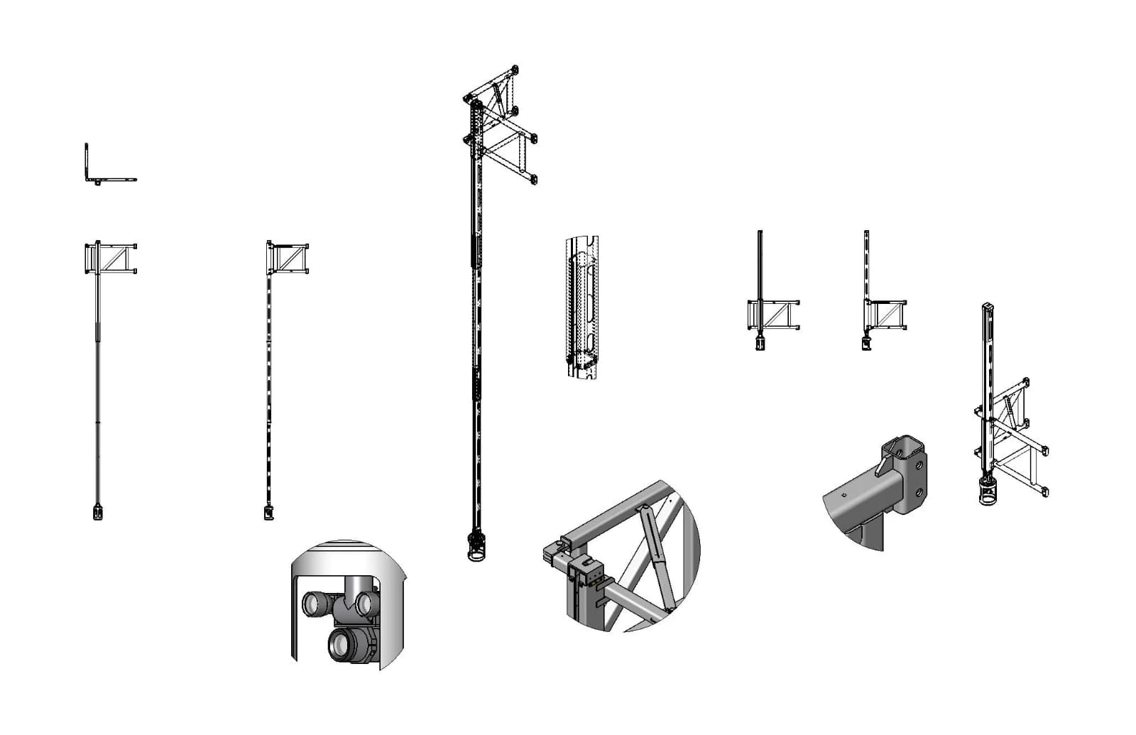
The Guide Wire Inspection System deploys a camera and lighting frame from a winch to inspect the LMRP and BOP. A monitor/control station operates the package. SIDUS identifies two SS172 lights, an SS420 color zoom camera and an SS109 or SS250 pan/tilt in its documented example; alternative equipment and intervention functions can be specified for the project.
Portable deployment and video/control functions.
250 W lamps in the documented example.
Published example uses the SS420 series; current housing and optics must be selected.
Historical assembly alternatives; confirm current model revision and mechanical fit.
SIDUS can configure intervention capability and alternative camera, lighting and pan/tilt products. The public drawing is an example, not a current universal bill of materials.
Only a 103×113 product thumbnail is published; use the official system drawing as a labelled illustration if no higher-resolution original is available. Current manual and project drawing required.
Historical project or assembly example. Equipment, wiring, dimensions and supply are configuration-specific. Request the current delivered-system drawing and operating instructions.
Product advice
Tell us about your application, operating conditions and preferred configuration.
These links open your email app. Send the email to submit your enquiry; demonstration dates and configuration are confirmed by ROVITEC.
roy@rovitec.noField-serviceable aluminum subsea halogen light with selectable reflector and lamp.
Explore product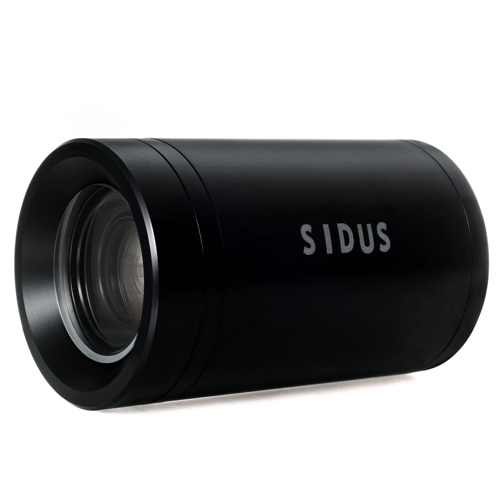
Family overview
Compare the SS420 Series models by housing material, depth rating and installation requirements.
Explore product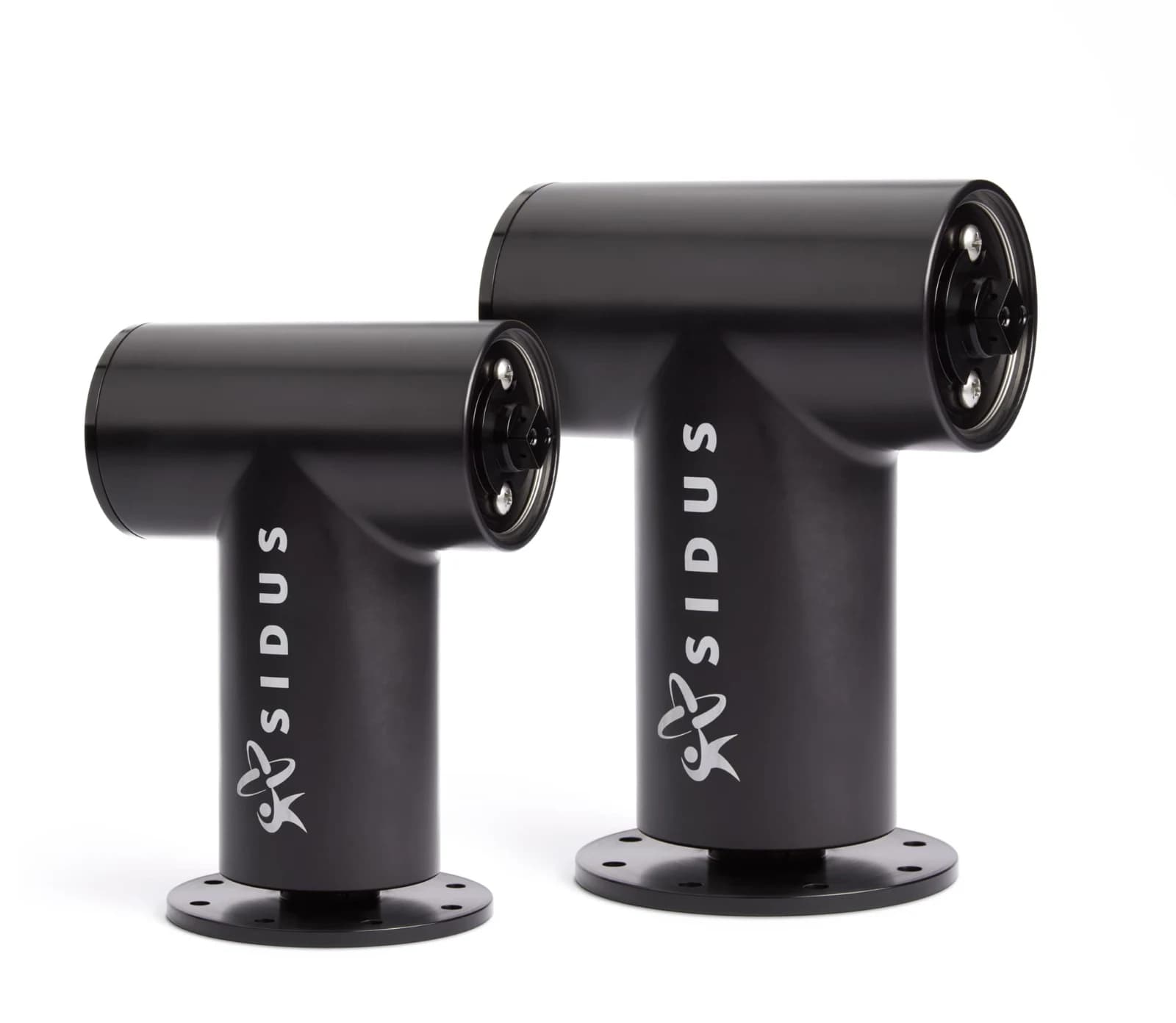
High-torque anodized 6061-t6 aluminum positioner for heavy subsea camera and sensor payloads.
Explore product